One stable setup is the goal
The most important rule is simple: once the EVB is wired correctly, it should stay on the bench and remain connected. The engineer should not need the board shipped back and forth, and the local team should not need to press buttons, move jumpers, or reconnect probes unless the hardware itself changes.
This is normal industry practice. Early firmware and system validation should happen on an EVB or bring-up board that exposes the signals engineers need. After the firmware behavior, hardware assumptions, power behavior, interfaces, and test cases are validated, the team can move toward the real-size product board with less risk.
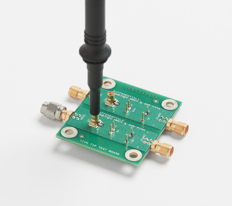
Product idea
   ↓
EVB / bring-up board with debug access
   ↓
Remote firmware, driver, RTOS, power, and integration validation
   ↓
Known-good behavior and hardware assumptions
   ↓
Final product-size board
What the remote bench looks like
The remote engineer works through a host PC in the client lab. That PC is connected to the EVB and to the lab instruments. From the engineer's side, the daily workflow is remote desktop or SSH into the host PC, then use scripts, debugger tools, serial logs, analyzer software, and power-unit software exactly as if sitting beside the bench.
Remote engineer
   │  VPN / RDP / SSH
   ▼
Client lab PC
   ├── USB/JTAG/SWD debugger ──────► target chip flash/reset/debug
   ├── UART / USB log adapter ─────► boot logs, RTOS logs, modem logs
   ├── Quasar relay / USB relay ───► board reset, chip reset, GPIO toggle
   ├── Saleae logic analyzer ──────► UART/SPI/I2C/GPIO timing capture
   ├── Power unit / analyzer ──────► power cycle, voltage/current measurement
   └── Optional camera ────────────► LEDs, display, mechanical state

EVB stays wired in one place unless hardware changes.
Real equipment examples
These are not the only possible tools, but they show the kind of equipment that makes remote hardware work practical. The exact brand can change. The important point is that the remote engineer can control reset/GPIO, capture real signals, and measure power from the lab PC.
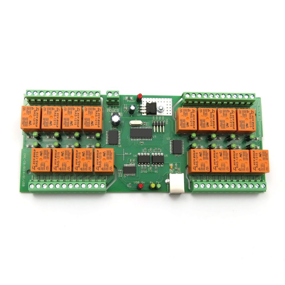
USB relay for reset and GPIO
A Quasar relay or similar USB relay can short reset pins, toggle boot-mode straps, or simulate slow GPIO events from a remote script.
Example source →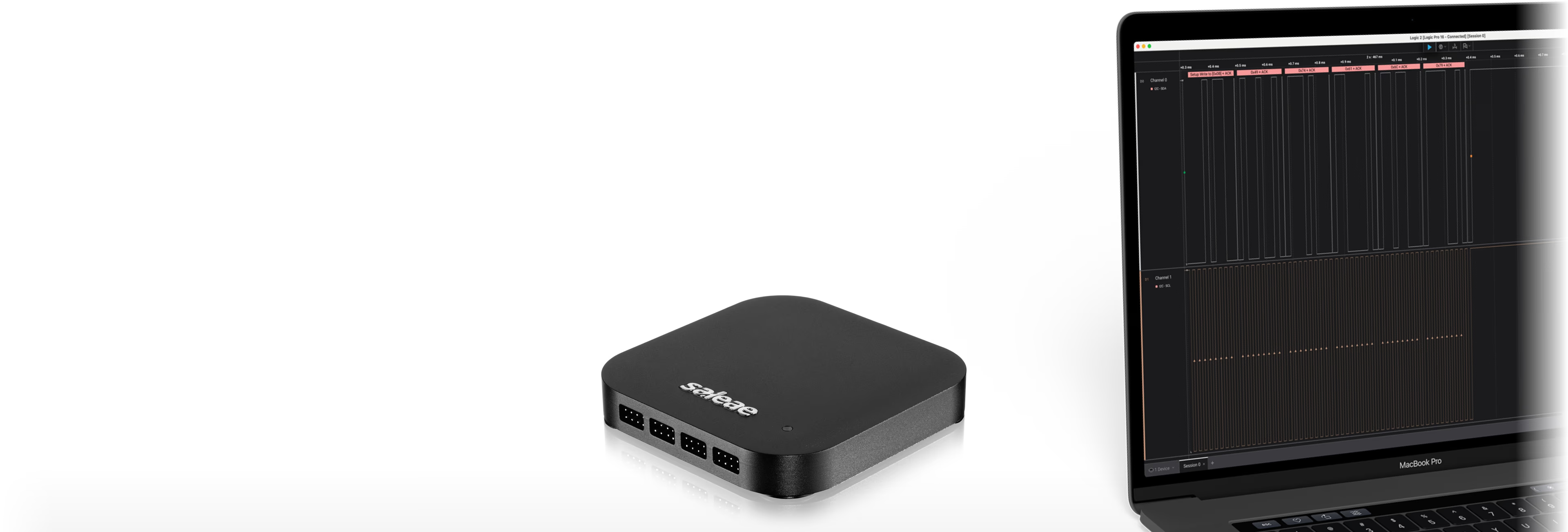
Saleae logic analyzer
Leave probes on UART, SPI, I2C, reset, wake, and interrupt pins so timing evidence can be captured without moving the board.
Example source →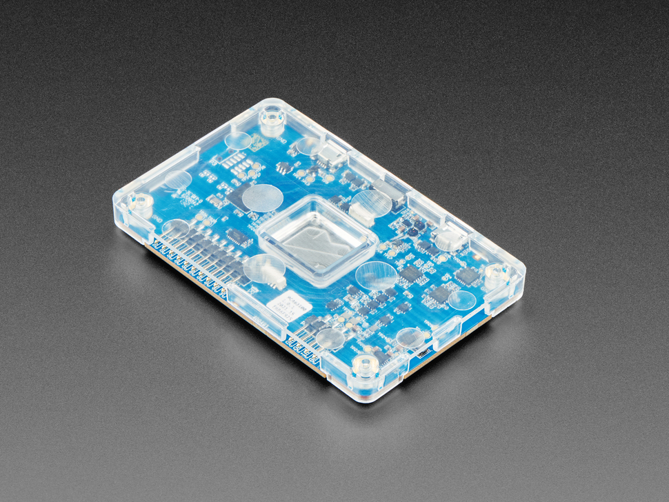
Power measurement unit
A USB-connected power profiler or programmable supply lets the engineer measure sleep current, wake spikes, active current, and power-cycle recovery.
Example source →How board reset works remotely
Board reset is usually controlled by wiring a relay contact across the physical reset button or to the EVB reset input. In the Qualcomm-style setup described here, a Quasar relay was used for reset and GPIO control. The relay is connected to the lab PC, and the remote engineer triggers it by software.
Reset path
Remote PC → Quasar relay → short RESET_N to GND → EVB resets
Why it matters
A firmware crash, modem lockup, bad boot state, failed update, or repeated boot test can be recovered without asking somebody local to press a button.
What the EVB should expose
Dedicated reset header or reset-button pads, clear ground reference, safe voltage level, and documented active level.
This is especially important for bootloader, watchdog, low-power wake, secure boot, and firmware-update work because those features must be tested across many reset and recovery cycles.
How chip reset works remotely
Board reset and chip reset are not always the same. A full board reset may restart the whole EVB, while a chip reset may target only the MCU, modem, radio, sensor, PMIC domain, or FPGA. A mature EVB exposes these reset lines separately when the product needs that level of control.
Debugger reset
JTAG/SWD tools can reset, halt, flash, and inspect the target chip when the debug port is connected to the lab PC.
Relay or GPIO reset
A Quasar relay or USB GPIO adapter can drive CHIP_RESET_N, modem reset, sensor reset, boot-mode selection, or factory-mode pins.
Power-domain reset
A programmable supply or load switch can remove power from one rail when reset is not enough to recover a peripheral.
How GPIO is toggled remotely
For simple digital control, a remote relay or USB GPIO board can simulate external events. This can represent a button press, wake pin, boot-mode pin, factory-mode strap, external interrupt, modem-control signal, or another board's request line.
Remote script
   ↓
Quasar relay / USB GPIO
   ↓
EVB GPIO input
   ↓
Firmware sees button, wake source, interrupt, boot strap, or control signal
A relay is excellent for reset-style signals and slower on/off control. It is not the right tool for high-speed timing generation. If a test needs fast pulses or precise waveform timing, the setup should use a signal generator, helper MCU, FPGA, or pattern generator.
How Saleae logic capture works remotely
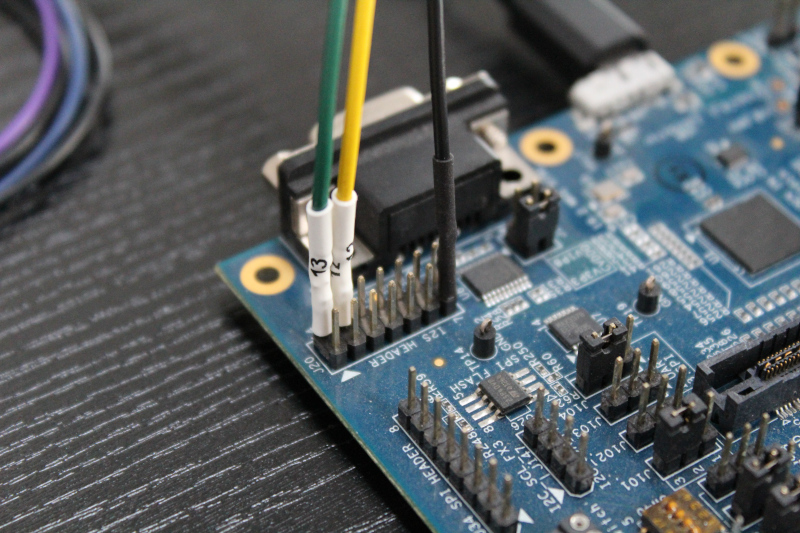
A logic analyzer is connected to the EVB once and left attached to useful debug headers. The Saleae connects to the lab PC over USB, and the remote engineer controls the capture software from the remote session. This is often more useful than a camera because it shows the actual signal timing.
Useful channels
Reset, boot mode, wake GPIO, interrupt lines, UART TX/RX, SPI, I2C, chip-select, power-enable, and status pins.
Useful captures
Boot timing, wake timing, UART logs, SPI/I2C transactions, interrupt timing, GPIO pre-notification, and firmware-vs-hardware timing mismatch.
Automation
Saleae Logic 2 can be controlled through automation APIs, so repeatable captures can be scripted around reset, flashing, or test execution.
For example, a firmware log might say that a GPIO was toggled before a modem event. A logic analyzer proves whether the pin really changed at the required time and whether the external device would have seen it.
How power measurement works remotely
For battery products, cellular modems, low-power devices, and boot/update recovery, remote power control is a major productivity multiplier. A USB/LAN programmable power unit or power analyzer is connected to the lab PC. The remote engineer can turn power on/off, set voltage, apply current limits, and measure current without touching the bench.
Remote engineer
   ↓
Lab PC power software / script
   ↓
Programmable supply or power analyzer
   ↓
EVB power input or measured rail
   ↓
Boot current, active current, sleep current, wake spike, recovery behavior
The EVB should reserve measurement jumpers or current-sense access points so important rails can be measured cleanly. This avoids cutting traces later and makes low-power validation much more believable.
- Cold boot and repeated power-cycle testing.
- Current limit and brownout-style recovery behavior.
- Sleep current, wake current, and active current measurement.
- Power-loss during firmware update or Flash programming.
- LTE attach, BLE advertising, sensor sampling, and other current-heavy operations.
Where a camera helps, and where it does not
A camera is useful for LED status, displays, motors, fixtures, connectors, and physical movement. It is not the main tool for most firmware root-cause work. In modem and low-power firmware work, logs, traces, reset control, GPIO timing, and power measurement usually give better evidence than a video feed.
What can be developed remotely
With this setup, remote development can cover much more than small code changes. It can support real firmware bring-up, driver work, RTOS behavior, boot/update work, power behavior, and integration debugging.
- Board bring-up when power, reset, boot logs, and debug access are available.
- Firmware flashing, bootloader behavior, secure boot, DFU, and update recovery.
- GPIO, UART, SPI, I2C, USB, BLE, modem-control, and sensor-interface debugging.
- RTOS task timing, interrupt handoff, queue behavior, race conditions, and deadlock recovery.
- Low-power entry/exit, wake sources, sleep current, peripheral restore, and current spikes.
- Repeated regression tests where the board must be reset, flashed, measured, and logged many times.
What still needs local hands
Remote hardware development is powerful, but it is not magic. The setup needs honest boundaries. Somebody local is still needed when the board must be reworked, a probe must move to a new signal, a jumper or connector must change, a damaged board must be replaced, or a mechanical/RF/analog issue needs physical lab work.
The point is not to remove the lab. The point is to make the lab remotely usable so the expensive engineering time is spent on firmware behavior, measurements, captures, and root cause instead of shipping boards and waiting for button presses.
Recommended client setup
EVB design
Reserve reset, boot-mode, GPIO, UART, JTAG/SWD, power-rail, current-measurement, and analyzer headers before ordering the board.
Remote control
Connect reset and important GPIO lines to a Quasar relay, USB relay, or USB GPIO controller with simple command-line scripts.
Evidence collection
Keep UART logs, debugger access, Saleae captures, and power measurement available from the same lab PC.
Recovery path
Make sure the engineer can recover a bad firmware image through debugger, ROM boot mode, DFU, UART bootloader, or controlled power cycle.